Direct Online Starter Animation Diagrams Electrical Online 4u
Therefore, in an open delta connection, two out of three transformers operate a three-phase load. The connection diagram of this system is shown in the figure below. Open Delta Connection (V-V Connection) The applied voltage in primary is; V AB, V BC, and V CA. The voltage induced in secondary is; V ab and V bc.

3 Phase 240V Motor Wiring Diagram Collection
The most common type of three-phase motor is that which has nine labeled (and often colored) wires coming out of the box on the side. There are many motors with more or fewer wires, but nine is the most common. These nine-wire motors may be internally connected with either a Wye (star) or a Delta configuration, established by the manufacturer.

+21 3 Phase Star Delta Motor Connection Diagram Pdf References Dakwah Islami
This is also the load phase voltage as it is delta-connected. vline = √3 × vphase. vline = √3 × 100V. vline ≈ 173.2VRMS. The delta-connected load will see a phase voltage that is the same as the line voltage, or 173.2 volts. From this we can determine the load current. iload = vphase Zload. iload = 173.2V 50Ω.
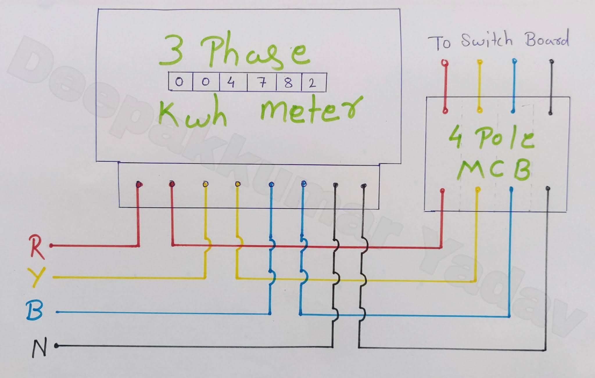
3 Phase Electric Meter Circuit Diagram
Transformer Winding Identification We now know that there are four different ways in which three single-phase transformers may be connected together between their primary and secondary three-phase circuits. These four standard configurations are given as: Delta-Delta (Dd), Star-Star (Yy), Star-Delta (Yd), and Delta-Star (Dy).

single phase 208v wiring
It provides internal connection diagrams for three-phase windings. It can be used with either concentric or lap windings. It also covers all possible parallels; wye and delta, 2 - 48 poles; part windings; two-speed windings; wye-delta and consequent-pole connections, 2 - 48 poles. It includes PAM connections, as well as triple- and quadruple.

3 Phase Motor Wiring Diagram 12 Leads
A three-phase transformer is built for a specific connection and voltage transformation and the unit will have a nameplate with the internal connections shown. When a single unit or bank of three is used, there are four types of connections. The four basic connections are: Y-Y, Y-∆, ∆-Y, and ∆-∆. The first symbol indicates the connection of the primary, and the second symbol is the.
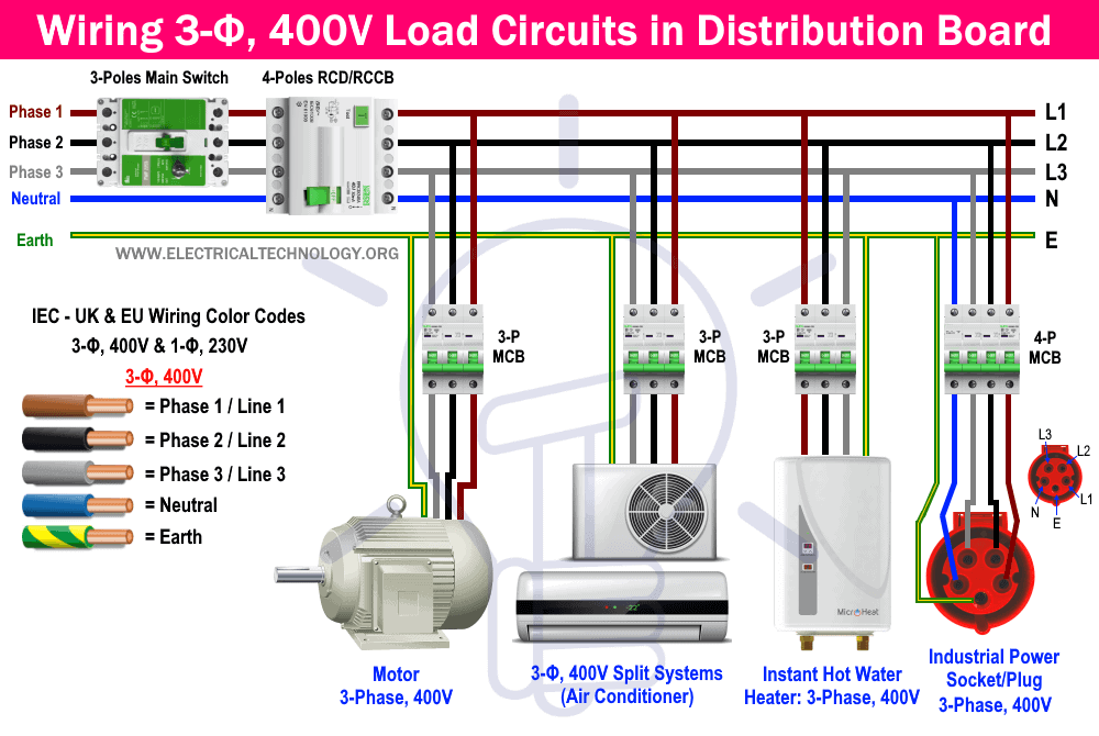
Three Phase Electrical Wiring Installation in Home NEC & IEC
single-phase wiring diagrams always use wiring diagram supplied on motor nameplate. w2 cj2 ui vi wi w2 cj2 ui vi wi a cow voltage y high voltage z t4 til t12 10 til t4 t5 ali l2 t12 ti-blu t2-wht t3.org t4-yel t5-blk t6-gry t7-pnk t8-red t9-brk red tio-curry tii-grn t12-vlt z t4 til t12
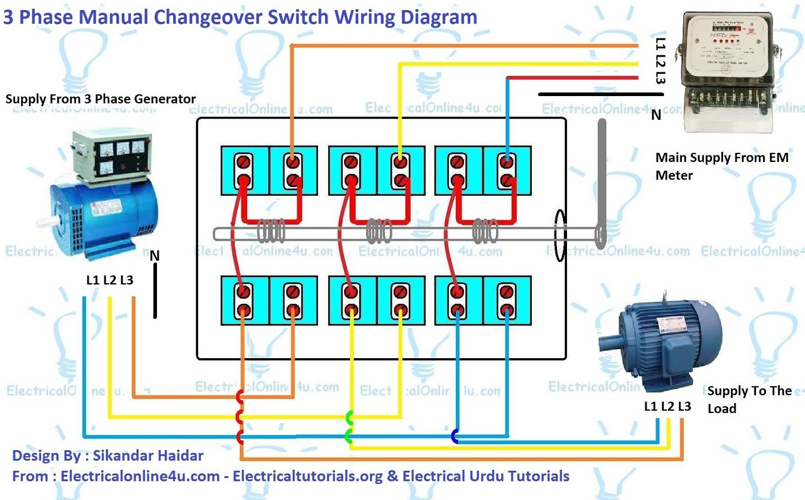
Electrical 3 Phase Switch Wiring Diagram
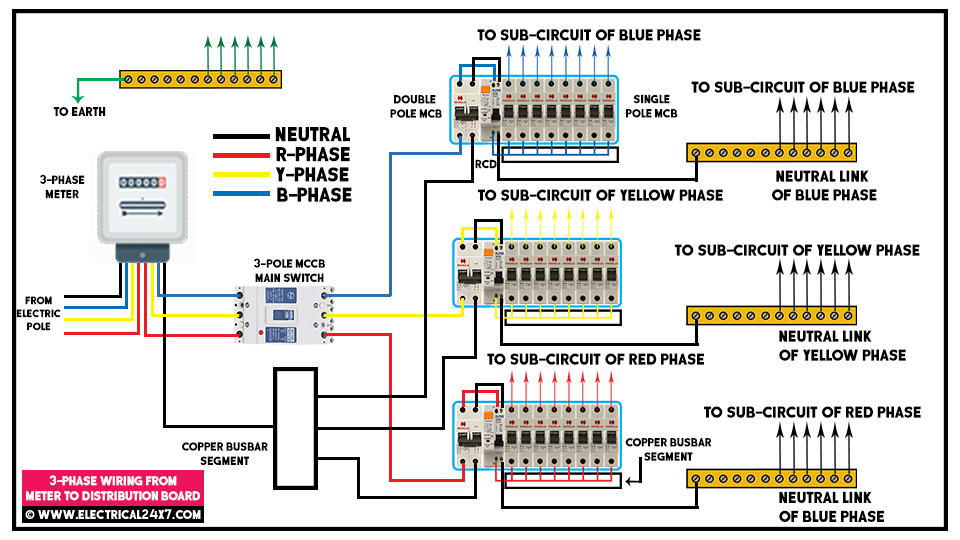
All the three Lines (Phases) are connected to the three or four pole main switch MCB (Miniature Circuit Breaker) or MCCB (Molded Case Circuit Breaker). In case of 4 poles MCB/MCCB, the neutral should be connected to the neutral terminal mentioned on the breaker otherwise, connect the neutral directly to the neutral busbar terminal in the panel.
3 Phase Diagram Electric Panel
Three-phase voltage transformations can be accomplished by using three phase transformers, which are single devices with all windings constructed on a single iron core. They also can be accomplished by using three single-phase transformers that are connected externally to form a three-phase bank.

How to Wire Voltmeters For 3 Phase Voltage Measuring
Three Phase Electrical Wiring Installation Diagrams - US -NEC Three Phase Electrical Wiring Installation Diagrams - UK, EU - IEC How to Connect Single Phase 120V Loads in a 1-Phase Wiring Distribution System? - NEC - US How to Connect Three Phase, 400V Loads in a 3-Phase Wiring Distribution System? - IEC & UK
ac hour meter wiring diagram
Wiring Procedure Step 1: Identify the Wires Identify and sort the 9 or 10 wires. 3 are power wires, and 6 or 7 come from the motor. The wires are color-coded, but some also have numbers written on them. Refer to the wiring diagram on the motor's label. Video | Wayne's Garage Step 2: Choose a Configuration Which configuration should you make?
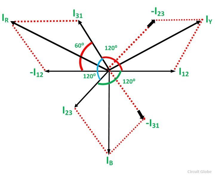
Delta Connection in a 3 Phase System Relation between Phase & Line Voltage & Current Circuit
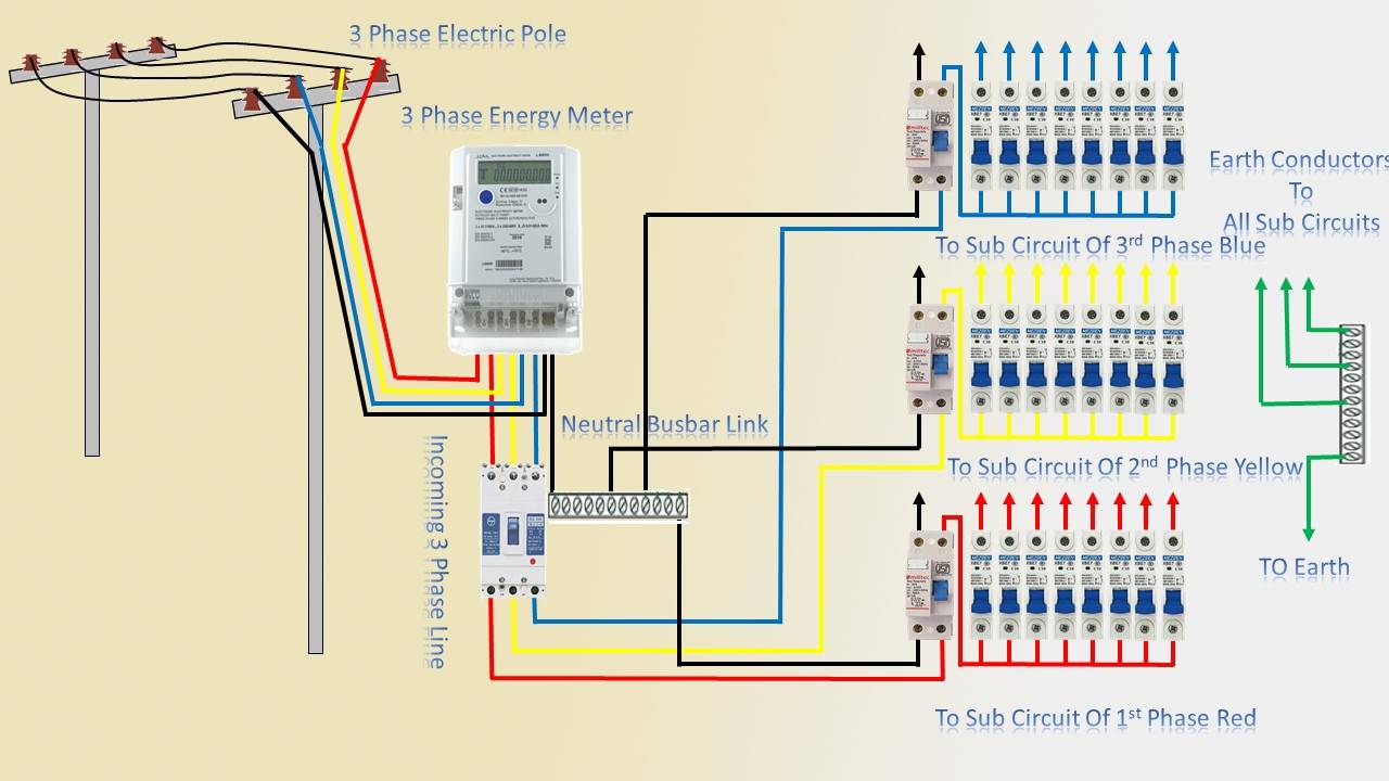
The figure below shows schematic diagram for industrial three phase wiring. Three phase power from the utilities is connected to the main breaker through three-phase energy meter. The power in the main breaker is then given to various busbars.
3 Phase Connection Diagram Deltrix Chargers
What is Delta Connection (Δ)? Delta or Mesh Connection (Δ) System is also known as Three Phase Three Wire System (3-Phase 3 Wire) and it is the most preferred system for AC power transmission while for distribution, Star connection is generally used.. In Delta (also denoted by Δ) system of interconnection, the starting ends of the three phases or coils are connected to the finishing ends of.

Three Phase Star Connection (Y) Three Phase Power,Voltage,Current Electrical Academia
The 120º phase difference of the three phases is must for the proper working of the system. Otherwise, the system becomes damaged. Types of Connections in Three-Phase System. The three-phase systems are connected in two ways, i.e., the star connection and the delta connection. Their detail explanation is shown below.

Wiring A 3 Phase Motor перевод Kira Wiring
Three-phase electric power (abbreviated 3φ [1]) is a common type of alternating current (AC) used in electricity generation, transmission, and distribution. [2]
.jpg)
A 3 Phase Motor Connection Wiring Diagram and Auxiliary Diagram (Star) Electrical And
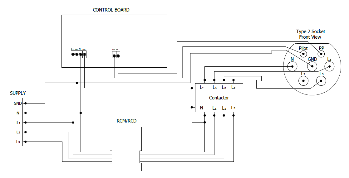
1 In Thailand we usually use 3 phases (L1, L2, L3) + Neutral (N) + Ground (PE) with 220V. A machine imported from Taiwan has four connectors: L1, L2, L3 and Ground (connected to the housing). It uses this mainly for motor controllers ( SDB-075A2 ), some relays and motors.